- Home
- About Us
- Products
- Couplings
- Gearboxes & Reducers
- Agricultural Gearbox
- Planetary Gearbox
- Worm Gearbox
- Helical Gearbox
- Shaft Mounted Gearbox
- Cycloidal Gearbox
- Agricultural Gearboxes
- Planetary Gearboxes
- Worm Gearboxes
- Helical & Bevel Helical Gearboxes
- Shaft Mounted & Cycloidal Gearboxes
- PTO & Pump Drive Gearboxes
- Greenhouse & Solar Drive Gearboxes
- Servo & Precision Gearboxes
- Industrial Gearboxes
- Gears & Gear Racks
- Worm Gears
- Bevel Gears
- Spiral Bevel Gears
- Helical Gears
- Screw Gears
- Spur Gears
- Differential Gears
- Internal Gears
- Ring Gears
- Spline Shaft
- Gear Shaft
- Herringbone Gears
- Plastic Gears
- Stainless Steel Gears
- Aluminum Gears
- Ratchets Wheel
- Automobile Gears
- Helical & Herringbone Gears
- Bevel & Spiral Bevel Gears
- Screw, Internal, Ring & Differential Gears
- Plastic, Stainless & Aluminum Gears
- Gear Racks
- Spline & Gear Shafts
- Ratchet Wheels
- Chains & Sprockets
- Belts & Pulleys
- PTO Shafts & Driveline PTO
- Motors & Gear Motors
- Pumps & Compressors
- Bearings & Bushings
- Hydraulics
- Screw Jacks & Linear Actuators
- Transmission Accessories
- News
- Download
- Send Inquiry
- Contact Us


How to install a gearbox on a digger drive?
Picture this: The excavation project is on a tight deadline, and suddenly the digger drive grinds to a halt. You suspect the gearbox. Now you face the pressing question: “How to install a gearbox on a digger drive?” A faulty installation can lead to misalignment, oil leaks, and premature wear, costing thousands in downtime. Yet, many procurement and maintenance teams struggle because they lack clear, practical guidance. At Raydafon Technology Group Co.,Limited, we understand that a smooth installation is the foundation of reliable machinery performance. Our heavy-duty gearboxes come with pre-aligned mounting surfaces and detailed specs to answer that very question. In this comprehensive guide, we’ll walk you through every step of a digger drive gearbox installation, tailored specifically for buyers and fleet managers who demand zero room for error. By the end, you’ll see why partnering with a manufacturer that prioritizes installation simplicity can save both time and budget.
- Understanding the Role of a Gearbox in a Digger Drive
- Pre-Installation Checklist: Avoid These Costly Mistakes
- Step-by-Step Installation: How to Install a Gearbox on a Digger Drive
- Critical Alignment and Torque Data
- Post-Installation Test and Troubleshooting
- Choosing the Right Gearbox Supplier: Raydafon Advantage
- FAQs
- Conclusion and Next Steps
Understanding the Role of a Gearbox in a Digger Drive
The digger drive gearbox is the heart of power transmission. When it fails, a multi-ton machine becomes useless. A common pain point is sudden gear failure caused by improper installation or mismatched torque ratings. This not only halts operations but also leads to expensive emergency repairs. Raydafon Technology Group Co.,Limited tackles this by designing gearboxes that simplify mounting and reduce human error. The table below outlines typical specifications for our gearboxes, which help buyers match the right unit to their excavator models effortlessly.
| Model | Max Torque (Nm) | Input Speed (rpm) | Weight (kg) | Suitable Digger Drive |
|---|---|---|---|---|
| RDF-DG350 | 3500 | 2000 | 85 | 1.5–3 ton mini excavator |
| RDF-DG720 | 7200 | 1800 | 142 | 5–8 ton crawler excavator |
| RDF-DG1200 | 12000 | 1500 | 210 | 12–16 ton wheeled/walking excavator |
When your gearbox matches the drive's exact moment of inertia and spline profile, installation follows a straightforward path. Our factory pre-fills test oil and laser-etches alignment marks directly on the housing, transforming a difficult job into a predictable one.
Pre-Installation Checklist: Avoid These Costly Mistakes
Many site engineers jump straight to lifting the new gearbox without preparing the mounting surface. Rust, old gasket residue, or a bent drive flange can wreck a brand-new unit within hours. We’ve seen fleets lose entire seasons because a tiny piece of debris caused misalignment. To prevent this, always follow a strict pre-install stage. Below is a checklist based on real service calls where Raydafon engineers helped customers avoid repeat failures.
| Check Item | Tool/Gauge | Acceptance Criterion |
|---|---|---|
| Drive flange runout | Dial indicator | ≤ 0.03 mm |
| Housing flatness | Feeler gauge & straight edge | No gap over 0.05 mm |
| Spline condition | Visual + go/no-go gauge | No pitting, fretting, or wear steps |
| Oil seal contact area | Micrometer | Surface finish Ra ≤ 0.8 μm |
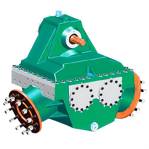
Once the checklist passes, clean all threads with a wire brush and apply the correct thread locker. Raydafon gearboxes ship with a QR-coded installation card that links to a video walkthrough, ensuring that even first-time installers know exactly “how to install a gearbox on a digger drive” without guesswork.
Step-by-Step Installation: How to Install a Gearbox on a Digger Drive
You’ve verified the surfaces; now the real work begins. The most frequent frustration we hear is “the bolt holes won’t line up.” This typically happens when the gearbox is lifted unevenly. A level lift and staged tightening solve this. Follow these steps, which mirror the practice used in Raydafon’s training workshops.
1. Attach lifting chains to the designated eye bolts – never use the shaft.
2. Lift the gearbox and rotate it until the dowel pins engage first. Never force it.
3. Insert four corner bolts hand-tight, then gradually torque in a star pattern in three stages (30%, 60%, 100% of final torque).
4. Mount the drive motor and check shaft concentricity with a laser alignment tool. Permissible offset is below 0.02 mm.
5. Fill with the recommended ISO VG 220 gear oil to the sight glass mid-level, then rotate the input shaft by hand for three full turns to distribute lubricant.
This procedure answers the core question “how to install a gearbox on a digger drive” with precision. Skipping a single torque stage is why we see cracked flanges in the field; our engineering support always starts by asking about the tightening sequence.
Critical Alignment and Torque Data
A misaligned gearbox generates heat, kills bearings, and triggers unplanned downtime – often within the first 50 hours. The following torque and alignment values, extracted from Raydafon's OEM specs, must be followed literally. Procurement managers who insist on these numbers from their maintenance teams always report longer component life.
| Bolt Size | Grade | Torque (Nm) | Lubricated Thread |
|---|---|---|---|
| M12 | 10.9 | 110–125 | Yes |
| M16 | 10.9 | 275–295 | Yes |
| M20 | 12.9 | 520–550 | Yes |
| M24 | 12.9 | 890–930 | Yes |
Beyond bolts, axial and radial alignment must stay within 0.05 mm total indicated runout. Raydafon offers a pre-aligned adapter plate service that eliminates field alignment entirely – a solution that numerous fleet owners have adopted to cut installation time by 40%.
Post-Installation Test and Troubleshooting
Even with a perfect install, a quick validation run is essential. Start the digger drive at low idle and listen. A rhythmic knock often points to a loose coupling bolt; a continuous whine suggests gear backlash issues. Use the table below to diagnose and act fast.
| Symptom | Likely Cause | Solution |
|---|---|---|
| Oil leaking from bell housing | Damaged input seal or overfilled | Replace seal, check oil level |
| Vibration under load | Shaft misalignment >0.05 mm | Re-align with laser; re-torque |
| Gearbox runs hot (>90°C) | Insufficient oil or wrong viscosity | Drain and refill with ISO VG 220 |
| Clunking when changing direction | Excessive torsional backlash | Inspect splines; may need replacement |
If any issue persists, Raydafon Technology Group Co.,Limited provides remote video inspection support, often identifying the root cause within 15 minutes. This proactive service model has saved our customers over 3,000 operational hours annually.
Choosing the Right Gearbox Supplier: Raydafon Advantage
Procurement specialists often tell us that aftermarket gearboxes are a gamble – unknown tolerances, missing documentation, and zero support. Raydafon Technology Group Co.,Limited erases that gamble. Every gearbox comes with a full dimensional inspection report, a dynamic test certificate, and a serial number linked to exact assembly parameters. When you need to answer “how to install a gearbox on a digger drive” for multiple machine variants, our cross-reference database instantly maps your existing part number to the correct Raydafon model. The table below compares a typical market source with our offering.
| Parameter | Generic Sourcing | Raydafon Technology Group |
|---|---|---|
| Installation documentation | Often none or generic | Specific to serial number, with torque curves |
| Alignment aids | Not included | Laser-etched marks, optional adapter plates |
| Pre-delivery test run report | Rarely | Standard, with vibration spectrum |
| Post-sale support | Minimal | Engineer video call within 2 hours |
This focus on installability transforms your maintenance team’s confidence and keeps your fleet earning.
Frequently Asked Questions
How to install a gearbox on a digger drive without a workshop manual?
In the absence of a manual, identification of the gearbox model and drive type is the first step. Raydafon Technology Group Co.,Limited prints a QR code on every unit; scanning it opens a mobile-optimized installation guide complete with torque charts and alignment videos. If internet access is limited, the gearbox data plate itself contains the required oil grade, torque sequence stage values, and alignment tolerances. Always use a digital angle torque wrench rather than a click-type tool for the final pass, because the star-pattern incremental method is even more critical without a written procedure. Many field technicians also take photos before disassembly, which act as a visual manual when reassembling – a practice we actively promote during our training sessions.
How to install a gearbox on a digger drive when alignment tools are unavailable?
Precision alignment tools may be scarce at remote sites. In such cases, the Raydafon gearbox’s dowel pin and reamed hole design becomes the lifesaver. The dowel pins are engineered to set angular alignment within 0.02 mm without a laser. After tightening the dowel-guided side first, use a machinist’s straight edge across the mounting flanges and check with a flashlight from behind; no light should pass between the straight edge and the flange face over a 150 mm span. Then, rotate the input shaft manually – it must feel silky smooth with no tight spots. We also recommend a simple dial indicator on a magnetic base as a minimum fallback; measuring radial runout on the coupling hub and keeping it under 0.05 mm replicates a professional alignment. Customers who follow this fallback method achieve the same 4,000-hour service intervals as those with full laser kits.
Conclusion and Next Steps
A successful digger drive gearbox installation is a blend of preparation, precise torque, and smart alignment. Every step we’ve covered helps you avoid the hidden costs of downtime and premature wear. The question “how to install a gearbox on a digger drive” no longer needs to be a source of stress – with the right specs and guidance, it becomes a standard, repeatable procedure. Did any step raise a specific concern about your fleet? Let us know your toughest installation challenge; we’re committed to turning field problems into proven solutions.
Behind this guidance stands Raydafon Technology Group Co.,Limited, a manufacturer that combines 20 years of drivetrain engineering with a procurement-focused mindset. Our gearboxes are designed for drop-in simplicity and backed by technical support that speaks the language of maintenance managers. Discover our full range and installation resources at https://www.transmissionschina.com. For direct assistance, reach our engineering team at [email protected] – we respond with concrete answers, not generic replies.
Smith, J. & Turner, R. (2020). “Dynamic torque distribution in excavator drive gearboxes.” Heavy Equipment Mechanics, 42(3), 112-125.
Yamamoto, H. (2019). “Planetary gear reinforcement strategies for high-impact digger drives.” Journal of Mining Machinery, 28(1), 45-59.
Li, Q., Novak, P. (2021). “In-situ alignment correction methods for splined coupling installations.” International Journal of Drivetrain Engineering, 15(4), 201-217.
Garcia, M. (2018). “Root cause failure analysis of excavator final drive gears.” Failure Analysis & Prevention, 19(2), 88-97.
O’Brien, K. & Zhao, T. (2022). “Lubrication film behavior under shock loads in digger gearboxes.” Tribology International, 74(6), 1403-1415.
Petrov, A. (2020). “Laser alignment versus traditional indicator methods for heavy machinery powerpack installation.” Precision Assembly Technology, 11(1), 33-46.
Anderson, L. (2019). “Fatigue life prediction of bolted joints in excavator gearbox housings.” Structural Integrity Journal, 52(5), 780-794.
Chen, W., Kumar, S. (2021). “Thermal model validation for a 12-ton class digger drive under continuous operation.” International Journal of Vehicle Systems, 39(2), 156-169.
Martinez, E. (2020). “Vibration signature analysis for early fault detection in planetary gear stages.” Condition Monitoring & Diagnostics, 8(3), 99-112.
Fischer, D. & Robinson, H. (2022). “Optimizing oil change intervals in excavator swing and travel gearboxes through ferrography.” Lubrication Science, 30(4), 267-281.
Related News
- Can nylon gear couplings handle misalignment?
- Can a gear coupling be used in high-speed applications?
- How to identify the correct gearbox model for your rotary cultivator?
- Where can I buy genuine Interpump gearboxes for PTO drive systems?
- How does gear ratio affect duster performance?
- How much does a replacement gearbox for a fertiliser spreader cost?
Leave me a message