- Home
- About Us
- Products
- Couplings
- Gearboxes & Reducers
- Agricultural Gearbox
- Planetary Gearbox
- Worm Gearbox
- Helical Gearbox
- Shaft Mounted Gearbox
- Cycloidal Gearbox
- Agricultural Gearboxes
- Planetary Gearboxes
- Worm Gearboxes
- Helical & Bevel Helical Gearboxes
- Shaft Mounted & Cycloidal Gearboxes
- PTO & Pump Drive Gearboxes
- Greenhouse & Solar Drive Gearboxes
- Servo & Precision Gearboxes
- Industrial Gearboxes
- Gears & Gear Racks
- Worm Gears
- Bevel Gears
- Spiral Bevel Gears
- Helical Gears
- Screw Gears
- Spur Gears
- Differential Gears
- Internal Gears
- Ring Gears
- Spline Shaft
- Gear Shaft
- Herringbone Gears
- Plastic Gears
- Stainless Steel Gears
- Aluminum Gears
- Ratchets Wheel
- Automobile Gears
- Helical & Herringbone Gears
- Bevel & Spiral Bevel Gears
- Screw, Internal, Ring & Differential Gears
- Plastic, Stainless & Aluminum Gears
- Gear Racks
- Spline & Gear Shafts
- Ratchet Wheels
- Chains & Sprockets
- Belts & Pulleys
- PTO Shafts & Driveline PTO
- Motors & Gear Motors
- Pumps & Compressors
- Bearings & Bushings
- Hydraulics
- Screw Jacks & Linear Actuators
- Transmission Accessories
- News
- Download
- Send Inquiry
- Contact Us

Electric Motor Brake
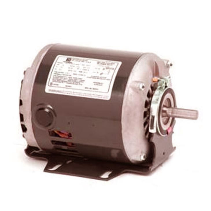
Electric Motor Brake is a spring-set fail-safe multiple disc brake designed for high torque in a compact envelope. The brake uses radially-spaced coil springs to keep the friction discs compressed against the armature when the coil is not energized — this is the "fail-safe" behavior that holds the load when power is removed. When the DC coil is energized, electromagnetic force overrides spring pressure and releases the friction discs for drag-free shaft rotation. Standard coil voltages are 24V, 48V, 90V and 190V DC. The brake ships ready for installation by sliding over the keyed motor shaft and bolting to a frame member. Optional C-face non-magnetic flanges allow direct mounting on C-frame motors without an adapter. Custom coil voltages, mounting flanges and disc stacks are available for OEM applications. Suitable for machine tool spindles, conveyors, hoists, packaging equipment and any application that requires positive holding when power is removed.
Raydafon · EFS Series Electric Motor Brake · Spring-Set Multiple Disc Fail-Safe Design
Electric Motor Brake — Spring-Set Multiple Disc Fail-Safe Brake for C-Face Motor Mounting
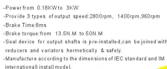
The Electric Motor Brake is a spring-set fail-safe multiple disc brake that provides unusually high torque for its compact size. The brake uses radially-spaced coil springs between the armature and the end plate to keep the friction discs compressed against the armature. This produces a constant holding force whenever the coil is not energized — the definition of a fail-safe brake. If power is lost during operation, the brake engages automatically and holds the load.
When the DC coil is energized, electromagnetic force flows through the flux path to override spring pressure and releases the friction discs, allowing drag-free rotation of the shaft. Standard coil voltages are 24V, 48V, 90V and 190V DC. The brake ships ready for installation by sliding the unit over the keyed motor shaft and bolting it to a frame member. Optional C-face non-magnetic flanges allow direct mounting to C-frame motors without an adapter plate.
Brake TypeSpring-Set Fail-SafeMultiple disc design
ActionFail-SafeHolds when de-energized
Coil Voltage24V - 190V DCCustom voltages available
MountingKeyed Shaft / C-FaceSlide-on installation
How a Spring-Set Electric Motor Brake Works
Operating PrincipleThe operating principle of a spring-set electric motor brake is fundamentally different from a hydraulically or pneumatically actuated brake. Understanding the three-state cycle below is essential to selecting the correct brake for a given application — particularly the fail-safe behavior that makes this brake type the standard for hoists, cranes and any vertical-axis load that must not fall when power is interrupted.
State 01 · De-Energized
Brake Engaged — Springs Hold the Load
With the coil de-energized, radially-spaced coil springs between the armature and end plate push the friction discs into contact with the armature and the shaft hub. The friction engagement holds the shaft against rotation. This is the brake's default state — it does not require any power to hold the load, which is why it is called fail-safe.
State 02 · Energized
Brake Released — Coil Overrides Springs
When DC current flows through the coil, electromagnetic force is generated through the flux path. This force pulls the armature against the spring pressure, releasing the friction discs from contact. With the discs released, the shaft rotates freely without drag. The release force is dimensioned to reliably overcome the spring force plus the friction force at the rated torque.
State 03 · Power Loss
Brake Re-Engages Automatically
If the DC supply is interrupted — whether from a power failure, an emergency stop signal or a deliberate coil de-energization — the coil field collapses within milliseconds and the springs re-engage the friction discs. The load is brought to a controlled stop by the brake torque. This is the fail-safe behavior: no external command or auxiliary power is needed to apply the brake.
Technical Specification — EFS Series Electric Motor Brake
Engineering ReferenceThe table below lists the standard specification of the Electric Motor Brake. For a replacement or OEM application, confirm the required brake torque, coil voltage, motor shaft diameter and mounting interface against the machine drawing before ordering.
| Parameter | Specification |
|---|---|
| Brake Type | Spring-set, fail-safe, multiple disc brake |
| Operating Principle | Spring pressure holds when de-energized; DC electromagnet releases when energized |
| Disc Configuration | Multiple friction disc stack with radial coil springs |
| Standard Coil Voltage | 24V DC, 48V DC, 90V DC, 190V DC |
| Custom Coil Voltage | Available on request for OEM applications |
| Torque Range | High torque relative to envelope size; specific values confirmed per frame |
| Engagement Time | Milliseconds after coil de-energization |
| Release Time | Milliseconds after coil energization |
| Friction Material | Wear-resistant friction discs suitable for dry running |
| Armature Material | High magnetic permeability steel for fast response |
| Coil Insulation | Class F (standard), other classes available |
| Standard Mounting | Slide over keyed shaft, bolt to frame member |
| C-Face Mounting | Optional non-magnetic C-face flange for direct C-frame motor mounting |
| Application Duty | Holding and emergency stop; not intended for frequent dynamic braking cycles without load confirmation |
| Customization | Coil voltage, torque rating, mounting flange, disc stack, shaft bore |
| Certification | ISO 9001 manufacturing system |
| Origin | Ningbo, China |
Why Specify the Raydafon Electric Motor Brake?
Design AdvantagesSix design characteristics separate this electric motor brake from a commodity unit. Each one addresses a specific consideration in fail-safe braking applications.
Fail-Safe by Design — No Power Required to Hold
The brake holds the load by spring force, not by electromagnetic force. This means the load is held even when the DC supply is lost, interrupted or deliberately switched off. For hoists, cranes, vertical conveyors and any application where a falling load would be dangerous, this property eliminates the need for a separate backup brake or mechanical lock.
High Torque in a Compact Envelope
The multiple disc design multiplies friction surface area within a small axial envelope. Multiple thin friction discs produce higher torque than a single thick disc of the same outer diameter because the total friction contact area is larger. This is why the brake can deliver unusually high torque without a large housing — a critical advantage in machine designs where axial space is constrained.
Fast Response Time
The armature is manufactured from high magnetic permeability steel, and the coil flux path is dimensioned to minimize the time between coil energization and brake release. Similarly, on de-energization the spring force applies the brake within milliseconds. This fast response is important in emergency stop sequences where the braking distance determines the safety distance of the machine guard.
Slide-On Keyed Shaft Installation
The brake ships ready for installation. The bore is keyed to match the standard motor shaft, so the brake slides over the shaft and bolts to a frame member. No special alignment jig or shimming is required. For retrofits, the existing motor shaft does not need to be modified — the key that drives the driven load also drives the brake hub.
Optional C-Face Flange for Direct Motor Mounting
C-face non-magnetic flanges are available for direct mounting on C-frame motors. The non-magnetic flange isolates the brake's magnetic circuit from the motor end bell and prevents flux leakage that could affect motor performance. With the C-face option, the brake and motor become a single mechanical assembly that mounts to the machine as one unit.
ISO 9001 Manufacturing and Full Traceability
Every brake is assembled under an ISO 9001 quality system. Coil resistance, spring free length, disc thickness and bore concentricity are inspected in process. Each unit receives a functional test — engagement torque and release current — before packing. Batch material certificates are retained and available with the shipment.
Where the Electric Motor Brake Is Used
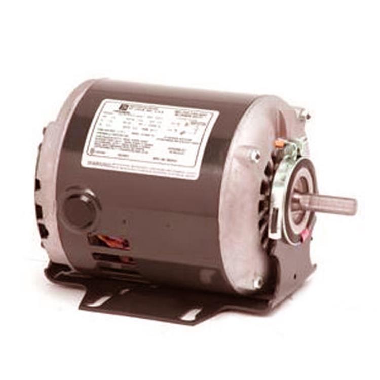
ApplicationsThe EFS Series is specified wherever a fail-safe holding brake is required on an electric motor. The applications below are the ones most often quoted on a Raydafon electric motor brake enquiry.
Hoists & Cranes
Overhead hoists, gantry cranes and jib cranes where a falling load must be prevented when power is removed.
Vertical Conveyors
Bucket elevators, vertical screw conveyors and indexing lifts where the load must be held between cycles.
Machine Tools
Spindle holding brakes, rotary table brakes and index table positioning mechanisms where fast release and repeatable engagement are required.
Packaging Machinery
Cartoners, labellers and wrapping machines where the brake holds the machine at a defined position between cycles.
Door & Gate Drives
Industrial roll-up doors, gates, barriers and shutters where the brake holds the door in position when the drive is de-energized.
Textile Machinery
Winding, unwinding and tension control equipment where the brake provides fast stop and precise holding.
Medical & Laboratory
MRI patient tables, scanner gantries and laboratory automation where the brake must release without drag and hold without drift.
OEM Machine Builds
Wholesale and OEM supply for machine builders who need a standard fail-safe brake integrated into a production line.
Spring-Set Electric Brake vs Other Brake Types
Selection GuideA common procurement question is how a spring-set electric motor brake compares to other common industrial brake types. The comparison below uses typical values at comparable torque for each type.
| Parameter | Spring-Set Electric | Permanent Magnet | Hydraulic | Pneumatic |
|---|---|---|---|---|
| Fail-Safe | Yes — holds without power | No — requires power to hold | Yes — spring return | No — requires air pressure |
| Power Source | DC electrical only | DC electrical only | Hydraulic pump | Air compressor |
| Response Time | Milliseconds | Milliseconds | Slower (valve + fluid) | Moderate |
| Torque Density | High (multiple disc) | Moderate | Very high | Moderate |
| Installation | Slide over keyed shaft, bolt to frame | Integrated in motor design | Requires hydraulic circuit | Requires air line and valve |
| Maintenance | Disc wear inspection only | Not serviceable | Fluid change, seal replacement | Air filter, seal replacement |
| Environmental | Unaffected by moisture, dust, temperature | Temperature sensitive | Sensitive to contamination | Sensitive to moisture in air |
| Best Suited For | Fail-safe holding on electric motors, hoists, cranes, machine tools | Compact motors with integrated brake | Heavy machinery with existing hydraulic power | Applications with existing compressed air |
How to Order the Electric Motor Brake
Ordering InputsTo confirm the correct EFS Series brake and issue a wholesale or OEM quotation, Raydafon needs the five items below. For a replacement unit, the original brake nameplate data, motor nameplate or a dimensioned drawing is usually sufficient.
Send These Five Details for an Electric Motor Brake Quotation
Send the five items below and Raydafon will confirm the model, torque, coil voltage, mounting interface and lead time within one working day.
- 01Required brake torque (N.m or lb-ft) at the motor shaft
- 02Motor shaft diameter and keyway dimensions
- 03Available DC coil voltage (24V / 48V / 90V / 190V or custom)
- 04Mounting configuration: frame-mounted, C-face motor, or foot bracket
- 05Quantity required and any environmental constraints (temperature, moisture, dust)
Talk to Raydafon About Your Electric Motor Brake Requirement
Whether you are replacing a worn fail-safe brake on an existing motor, specifying a new brake for an OEM machine build, or sourcing spring-set electric motor brakes in wholesale volume, Raydafon can quote to your torque, shaft diameter, coil voltage, mounting configuration and environmental requirements. OEM and project quantities supplied directly from the Ningbo factory. ISO 9001 certified.
Related Category
- Agricultural Gearbox
- Planetary Gearbox
- Worm Gearbox
- Helical Gearbox
- Shaft Mounted Gearbox
- Cycloidal Gearbox
- Agricultural Gearboxes
- Planetary Gearboxes
- Worm Gearboxes
- Helical & Bevel Helical Gearboxes
- Shaft Mounted & Cycloidal Gearboxes
- PTO & Pump Drive Gearboxes
- Greenhouse & Solar Drive Gearboxes
- Servo & Precision Gearboxes
- Industrial Gearboxes
Send Inquiry
Contact Info
-
Address
Luotuo Industrial Area, Zhenhai District, Ningbo City, China
-
Tel
-
Email


News Recommendations