- Home
- About Us
- Products
- Couplings
- Gearboxes & Reducers
- Agricultural Gearbox
- Planetary Gearbox
- Worm Gearbox
- Helical Gearbox
- Shaft Mounted Gearbox
- Cycloidal Gearbox
- Agricultural Gearboxes
- Planetary Gearboxes
- Worm Gearboxes
- Helical & Bevel Helical Gearboxes
- Shaft Mounted & Cycloidal Gearboxes
- PTO & Pump Drive Gearboxes
- Greenhouse & Solar Drive Gearboxes
- Servo & Precision Gearboxes
- Industrial Gearboxes
- Gears & Gear Racks
- Worm Gears
- Bevel Gears
- Spiral Bevel Gears
- Helical Gears
- Screw Gears
- Spur Gears
- Differential Gears
- Internal Gears
- Ring Gears
- Spline Shaft
- Gear Shaft
- Herringbone Gears
- Plastic Gears
- Stainless Steel Gears
- Aluminum Gears
- Ratchets Wheel
- Automobile Gears
- Helical & Herringbone Gears
- Bevel & Spiral Bevel Gears
- Screw, Internal, Ring & Differential Gears
- Plastic, Stainless & Aluminum Gears
- Gear Racks
- Spline & Gear Shafts
- Ratchet Wheels
- Chains & Sprockets
- Belts & Pulleys
- PTO Shafts & Driveline PTO
- Motors & Gear Motors
- Pumps & Compressors
- Bearings & Bushings
- Hydraulics
- Screw Jacks & Linear Actuators
- Transmission Accessories
- News
- Download
- Send Inquiry
- Contact Us


Worm Reducer Gearbox
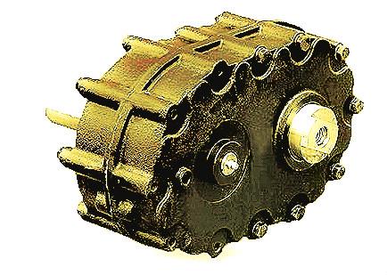
Worm Reducer Gearbox is a right-angle speed reduction unit that uses a hardened steel worm driving a bronze worm wheel to reduce motor input speed and multiply torque. Raydafon supplies two standard series: NMRV with die-cast aluminum alloy housing covering NMRV030 to NMRV150, and WP with cast iron housing covering WP40 to WP250. Rated power ranges from 0.06 kW to 15 kW with reduction ratios from 5:1 to 100:1 single-stage and up to 3600:1 multi-stage. Output torque ranges from 2.6 N.m to 1760 N.m. Input accepts IEC-normalized motor flange for direct coupling without an adapter. Single-stage efficiency ranges from 65% to 90% depending on ratio; self-locking is available on ratios above 30:1. Applications include conveyors, mixers, packaging lines, material handling and rotary indexing equipment. OEM customization on ratio, shaft, flange and mounting configuration.
Worm Reducer Gearbox — NMRV & WP Series Right-Angle Worm Speed Reducer
The Worm Reducer Gearbox is a right-angle speed reduction unit that transmits power between perpendicular shafts using a hardened steel worm driving a bronze worm wheel. Raydafon supplies two standard series: NMRV with die-cast aluminum alloy housing covering NMRV030 to NMRV150, and WP with cast iron housing covering WP40 to WP250. Rated power ranges from 0.06 kW to 15 kW with reduction ratios from 5:1 to 100:1 single-stage and up to 3600:1 multi-stage.
Output torque ranges from 2.6 N.m to 1760 N.m. The hollow shaft input with IEC-normalized motor flange accepts standard motors directly — no adapter, no coupling, no alignment. Single-stage efficiency ranges from 65% to 90% depending on ratio, and self-locking is available on ratios above 30:1 for holding applications. OEM customization covers ratio, shaft dimensions, flange type, mounting configuration and output type.
Power0.06-15kW
Ratio5:1-100:1
Torque2.6-1760N.m
HousingAl / Iron
What Is a Worm Reducer Gearbox and How Does It Work?
Working PrincipleA worm reducer gearbox transmits power between two perpendicular shafts using a worm (a screw-like gear) and a worm wheel (a bronze gear that looks similar to a spur gear). When a motor turns the worm, the screw thread pushes against the teeth of the worm wheel and rotates it. Because the worm has very few teeth (often one to four) and the wheel has many (typically 20 to 100), a single worm gear stage achieves reduction ratios between 5:1 and 100:1 — far higher than a single spur or helical gear stage can reach.
The critical design detail is that the worm and wheel slide against each other rather than roll. This sliding contact produces the high reduction ratio in a compact envelope and gives the worm gearbox its self-locking property at high ratios. It is also why worm gearbox efficiency is lower than that of a helical gearbox at the same torque — typically 65% to 90% for worm, versus 96% for helical. The lost energy appears as heat, which is why worm gearboxes are often fitted with cooling fins on the housing or oil sumps on the larger frame sizes.
The worm is machined from 20CrMnTi carburized steel, then hardened and ground to a mirror finish. The worm wheel is cast from tin bronze (CuSn12) or aluminum bronze depending on the ratio and load. The bronze is softer than the hardened worm — this is deliberate. In the event of an overload, the bronze wheel wears preferentially and protects the worm, which is the more expensive component to replace.
NMRV Series Worm Reducer — Aluminum Alloy Housing, NMRV030 to NMRV150
Lightweight SeriesThe NMRV series uses a die-cast aluminum alloy housing. It is the standard choice for general industrial machinery and OEM equipment where weight matters and the gearbox is mounted on a moving frame, an indexing table or a compact machine build.
| Model | Power Range | Output Torque | Ratio Range | Motor Flange | Output Type |
|---|---|---|---|---|---|
| NMRV030 | 0.06 – 0.18 kW | 2.6 – 5 N.m | 5:1 – 100:1 | 56B5 / 63B5 | Hollow / Solid |
| NMRV040 | 0.12 – 0.37 kW | 5 – 12 N.m | 5:1 – 100:1 | 56B5 / 63B5 | Hollow / Solid |
| NMRV050 | 0.18 – 0.75 kW | 10 – 24 N.m | 5:1 – 100:1 | 63B5 / 71B5 | Hollow / Solid |
| NMRV063 | 0.37 – 1.5 kW | 20 – 52 N.m | 5:1 – 100:1 | 71B5 / 80B5 | Hollow / Solid |
| NMRV075 | 0.55 – 2.2 kW | 40 – 92 N.m | 5:1 – 100:1 | 80B5 / 90B5 | Hollow / Solid |
| NMRV090 | 1.1 – 4 kW | 80 – 190 N.m | 5:1 – 100:1 | 90B5 / 100B5 | Hollow / Solid |
| NMRV110 | 2.2 – 7.5 kW | 150 – 380 N.m | 5:1 – 100:1 | 100B5 / 112B5 | Hollow / Solid |
| NMRV130 | 4 – 11 kW | 250 – 660 N.m | 5:1 – 100:1 | 112B5 / 132B5 | Hollow / Solid |
| NMRV150 | 5.5 – 15 kW | 400 – 1170 N.m | 5:1 – 100:1 | 132B5 / 160B5 | Hollow / Solid |

WP Series Worm Reducer — Cast Iron Housing, WP40 to WP250
Heavy-Duty SeriesThe WP series uses a cast iron housing and covers larger frame sizes with higher output torque capacity. Cast iron holds gear centre distance rigidly under shock load, making the WP series the standard for mining, construction, agricultural and heavy material handling applications.
| Model | Power Range | Output Torque | Ratio (Single-Stage) | Ratio (Multi-Stage) | Housing |
|---|---|---|---|---|---|
| WP40 | 0.12 – 0.75 kW | 11 – 32 N.m | 10:1 – 60:1 | Up to 900:1 | Cast iron |
| WP50 | 0.18 – 1.5 kW | 22 – 65 N.m | 10:1 – 60:1 | Up to 1200:1 | Cast iron |
| WP60 | 0.37 – 2.2 kW | 45 – 130 N.m | 10:1 – 60:1 | Up to 1500:1 | Cast iron |
| WP70 | 0.75 – 4 kW | 90 – 260 N.m | 10:1 – 60:1 | Up to 1800:1 | Cast iron |
| WP80 | 1.1 – 5.5 kW | 150 – 400 N.m | 10:1 – 60:1 | Up to 2400:1 | Cast iron |
| WP100 | 2.2 – 7.5 kW | 250 – 660 N.m | 10:1 – 60:1 | Up to 3000:1 | Cast iron |
| WP120 | 4 – 11 kW | 400 – 1050 N.m | 10:1 – 60:1 | Up to 3600:1 | Cast iron |
| WP135 | 5.5 – 15 kW | 600 – 1450 N.m | 10:1 – 60:1 | Up to 3600:1 | Cast iron |
| WP155 | 7.5 – 15 kW | 800 – 1700 N.m | 10:1 – 60:1 | Up to 3600:1 | Cast iron |
| WP175 / WP200 / WP250 | 11 – 15 kW | 1000 – 1760 N.m | 10:1 – 60:1 | Up to 3600:1 | Cast iron |
Why Specify the Raydafon Worm Reducer Gearbox?
Design AdvantagesSix design characteristics separate this worm reducer gearbox from a commodity unit. Each one is measurable in field service.
High Ratio in a Compact Envelope
A single worm gear stage achieves reduction ratios from 5:1 to 100:1. A helical gearbox would need two or three stages to reach the same ratio at much larger overall size. For machine designs where the drive envelope is constrained — packaging lines, indexing tables, OEM machinery — the worm gearbox often fits where nothing else will.
Self-Locking Above 30:1
At ratios above 30:1, the lead angle of the worm becomes smaller than the friction angle between worm and wheel. The wheel cannot drive the worm, so the output shaft holds position when input power is removed. This is used for hoists, index tables and any holding application without needing a separate brake.
Hardened and Ground Worm — Longer Wheel Life
The 20CrMnTi worm is carburized, hardened and then ground to a mirror finish below Ra 0.4. This reduces sliding friction against the bronze wheel, controls heat generation, and extends the bronze wheel life. A softer or less-finished worm would wear the wheel prematurely.
Direct IEC Motor Coupling
The hollow input shaft with IEC motor flange accepts IEC 56B5 through 160B5 motors directly. The motor shaft slides into the hollow input bore and the motor flange bolts to the gearbox input flange. No coupling, no adapter plate, no shaft alignment jig. Solid shaft input is available for non-IEC motors.
Six Mounting Orientations
The NMRV and WP housings are symmetric. The same unit can be mounted horizontally, vertically or on the side by repositioning the oil fill, drain and breather plugs. For OEM machinery builders this means one gearbox part number can serve multiple machine configurations, reducing spare parts inventory.
ISO 9001 Manufacturing and Full Traceability
Every unit is assembled in Raydafon's Ningbo factory under an ISO 9001 quality system. Worm and wheel gear profiles are inspected in process, housing bore concentricity is verified, and each unit receives a run-in test before packing. Batch material certificates are available with the shipment.

Worm Reducer vs Helical Gearbox — Selection Guide
Buyer ComparisonA common procurement question is whether to specify a worm reducer gearbox or a helical gearbox for a given application. The comparison below uses the same rated output torque for both types.
Worm Reducer Gearbox
Raydafon NMRV / WP Series
- ConfigurationRight-angle, 90° between input and output shafts
- Ratio Range5:1 to 100:1 single-stage
- Efficiency65% to 90% depending on ratio
- Self-LockingYes, above 30:1
- Heat GenerationHigher, cooling fins on large frames
- NoiseBelow 60 dB(A) at 1 m
- CompactnessHigh reduction ratio in a small envelope
- Best Suited ForCompact machinery, holding applications, low-power right-angle drives
Helical Gearbox
BRC / PC Series Comparison
- ConfigurationInline or parallel-shaft, input and output parallel
- Ratio Range3:1 to 54:1 two-stage, higher with more stages
- EfficiencyUp to 96% two-stage
- Self-LockingNo, brake required for holding
- Heat GenerationLow
- NoiseBelow 65 dB(A) at 1 m
- CompactnessLarger envelope for the same ratio
- Best Suited ForContinuous-duty drives where efficiency drives the payback, parallel-shaft layouts
Where the Worm Reducer Gearbox Is Used
ApplicationsThe NMRV and WP series are specified wherever a compact right-angle speed reduction is required. The applications below are the ones most often quoted on a Raydafon worm reducer enquiry.
01
Conveyors
Belt, roller and screw conveyors where the worm reducer mounts at the conveyor drive end at 90° to the belt direction.
02
Mixers & Agitators
Chemical, food and pharmaceutical mixers where the worm reducer drives the agitator shaft from the side of the tank.
03
Packaging Lines
Cartoners, labellers and fillers where the right-angle output fits inside the machine frame and drives a compact mechanism.
04
Material Handling
Bucket elevators, screw feeders and small hoists where the self-locking property holds the load when the motor stops.
05
Rotary Index Tables
Indexing tables and positioning mechanisms where a high ratio worm reducer provides smooth positioning with self-locking.
06
Door & Gate Drives
Industrial doors, gates and shutters where the worm reducer provides quiet operation and holds position without a brake.
07
Agricultural Machinery
Grain augers, feed conveyors and small PTO-driven equipment where the WP cast iron housing handles field conditions.
08
OEM Machine Builds
Wholesale and OEM supply for machine builders who need a standard worm reducer integrated into a production line.
How to Order the Worm Reducer Gearbox
Ordering InputsTo confirm the correct NMRV or WP model and issue a wholesale or OEM quotation, Raydafon needs the five items below. For a replacement unit, the original gearbox nameplate data or a dimensioned drawing is usually sufficient.
Send These Five Details for a Worm Reducer Quotation
Send the five items below and Raydafon will confirm the model, ratio, mounting and lead time within one working day.
01Required output torque (N.m) or power (kW)
02Required output speed (rpm) or reduction ratio
03Motor interface: IEC frame size or solid shaft input dimensions
04Output type: hollow shaft, solid shaft or output flange
05Mounting orientation and quantity required

Talk to Raydafon About Your Worm Reducer Gearbox Requirement
Whether you are replacing a worn worm reducer, specifying a new right-angle drive for an OEM machine build, or sourcing NMRV and WP series gearboxes in wholesale volume, Raydafon can quote to your ratio, torque, motor interface, output type and mounting requirements. OEM and project quantities supplied directly from the Ningbo factory. ISO 9001 certified.
Related Category
- Agricultural Gearbox
- Planetary Gearbox
- Worm Gearbox
- Helical Gearbox
- Shaft Mounted Gearbox
- Cycloidal Gearbox
- Agricultural Gearboxes
- Planetary Gearboxes
- Worm Gearboxes
- Helical & Bevel Helical Gearboxes
- Shaft Mounted & Cycloidal Gearboxes
- PTO & Pump Drive Gearboxes
- Greenhouse & Solar Drive Gearboxes
- Servo & Precision Gearboxes
- Industrial Gearboxes
Send Inquiry
Contact Info
-
Address
Luotuo Industrial Area, Zhenhai District, Ningbo City, China
-
Tel
-
Email


News Recommendations